 |
MD_MAX72xx LED Matrix Arduino Library
3.0
Library to control connected MAX72XX devices as a pixel array
|
 |
MD_MAX72xx LED Matrix Arduino Library
3.0
Library to control connected MAX72XX devices as a pixel array
|
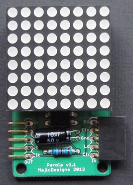
These custom modules allow a 'lego-like' approach to LED matrix display, using standard 8x8 on LED matrices. The software supports this flexibility through a scalable approach that only requires the definition of the number of modules to adapt existing software to a new configuration.

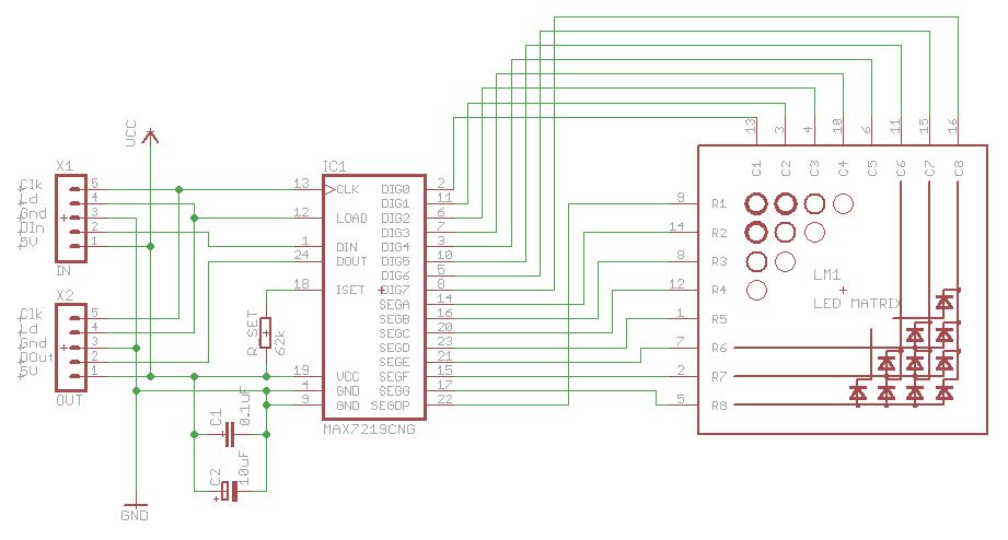
The schematic is the basic application circuit that is found on the MAX7219 datasheet, adapted to the LED matrix. Each Module consists of an 8x8 LED matrix controlled by a MAX7219 LED controller and a few passive components. These controllers can be daisy chained, making them ideal for the purpose.

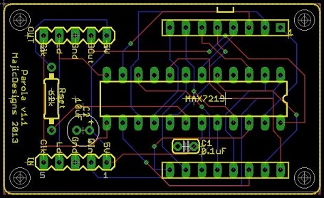
The PCB design was executed using the auto routing facility in Eagle CAD, and the PCB was manufactured by SeeedStudio. The Eagle CAD files for the layout and the Gerber files suitable for SeeedStudio are found on the Parola website. The final design includes edge connections that allow many modules to be connected together into an extended display, one LED module high.

How the LED matrix is wired is important for the library. The matrix used for library development was labeled 1088B and is sometime referred to as a common anode matrix. Connections should be made as described in the table below to be consistent with the assumptions in the software library.
| MAX Signal | MAX7219 Pin | MAX Signal | MAX7219 Pin |
|---|---|---|---|
| Dig0 (D0) | 2 | SegDP | 22 |
| Dig1 (D1) | 11 | SegA | 14 |
| Dig2 (D2) | 6 | SegB | 16 |
| Dig3 (D3) | 7 | SegC | 20 |
| Dig4 (D4) | 3 | SegD | 23 |
| Dig5 (D5) | 10 | SegE | 21 |
| Dig6 (D6) | 5 | SegF | 15 |
| Dig7 (D7) | 8 | SegG | 17 |
Segment data is packed on a per-digit basis, with segment G as the least significant bit (bit 0) through to A as bit 6 and DP as bit 7.
  G  F  E  D  C  B  A  DP
+------------------------+
| 7  6  5  4  3  2  1  0 | DIG0
|                      1 | DIG1
|                      2 | DIG2
|                      3 | DIG3
| O                    4 | DIG4
| O  O                 5 | DIG5
| O  O  O              6 | DIG6
| O  O  O  O           7 | DIG7
+------------------------+
  Vcc ----      ---- Vcc
 DOUT <---      ---< DIN
  GND ----      ---- GND
CS/LD <---      ---< CS/LD
  CLK <---      ---< CLK
Parola modules are connected by plugging them together.
